Model Properties
Each model in your scene has properties that control its appearance and behavior. Access these properties by selecting a model in the Models List or viewport.
Properties Panel Overview
When a model accordion item is opened, the left panel shows all available properties for that model:
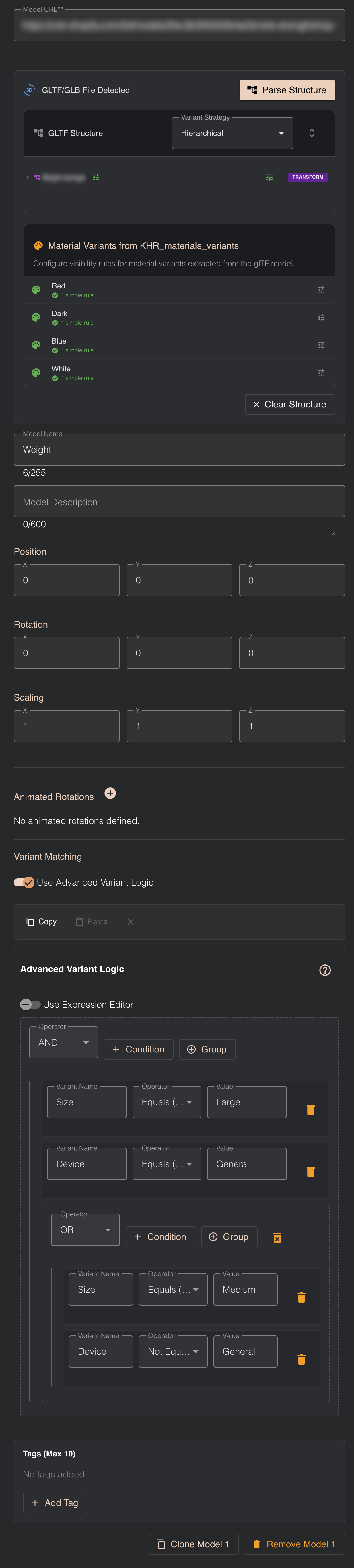
The properties panel is organized into logical sections that control different aspects of your model. Let's explore each property in detail.
Model URL
What it is: The public URL pointing to your hosted 3D model file, typically from Shopify CDN or another hosting service.
Example: https://cdn.shopify.com/s/files/1/0123/4567/files/chair.glb
Purpose: This is the source location of your 3D file. The Viewer Editor fetches the model from this URL when loading your scene.
Editing the URL: You can edit the URL field to point to a different file. However, be aware of the consequences:
If you change the URL after parsing the GLTF structure, all parsed node information will be lost, including:
- GLTF structure tree view
- Node-level variant matching configurations
- Material variant mappings
- Any node-specific settings you configured
You will need to click Parse Structure again and reconfigure all node-level settings for the new file.
When to Edit the URL:
- Updating to a newer version of the same model file
- Switching to an optimized version of the model
- Correcting a wrong URL shortly after adding the model
Best Practice:
- Use reliable hosting like Shopify CDN for fast, consistent loading times
- If making significant model changes, consider adding a new model instead of editing the URL to preserve your existing configuration as a backup
GLTF/GLB File Detection & Structure Parsing
Parse Structure Button
When it appears: When the Viewer Editor detects that your Model URL points to a GLTF or GLB file.
What it does: Clicking Parse Structure reads the internal structure of your GLTF/GLB file, revealing:
- All nodes (meshes, instanced meshes, transform nodes)
- Parent-child relationships between nodes
- Material variants (if using KHR_materials_variants extension)
When to use it:
- ✅ You want to show/hide individual parts of your model (e.g., chair legs, cushions, armrests)
- ✅ You want to switch materials using KHR_materials_variants
- ✅ You need to apply different variant logic to different parts
When you DON'T need it:
- ❌ You only want to show/hide the entire model as one unit
- ❌ You're loading simple models without internal parts
- ❌ You don't need material switching
Performance Note: Parsing structure adds a small processing step, so only use it when you need access to internal nodes or material variants.
GLTF Structure Tree View
What it shows: After parsing, you'll see a hierarchical tree view of all nodes within your GLTF file.
Node Types:
- Meshes - Visible geometry (the actual 3D shapes)
- Instanced Meshes - Duplicated geometry for performance
- Transform Nodes - Empty containers that organize other nodes
Parent-Child Relationships: Nodes can be nested, creating a hierarchy:
Chair (root)
├── Frame
│   ├── Leg_FL (front-left)
│   ├── Leg_FR (front-right)
│   ├── Leg_BL (back-left)
│   └── Leg_BR (back-right)
├── Seat
└── Backrest
Why it matters: You can apply variant logic to any level in this tree. For example:
- Hide all legs by targeting the "Frame" parent node
- Hide only the front-left leg by targeting "Leg_FL"
- Switch the entire chair by targeting the root node
Variant Strategy
What it controls: How variant logic affects child nodes when applied to parent nodes.
Available Strategies:
Hierarchical Strategy (Recommended)
When you apply variant logic to a parent node, all children are affected automatically.
Example:
Table (variant logic: show when size=large)
├── Top
├── Leg_1
├── Leg_2
├── Leg_3
└── Leg_4
With Hierarchical strategy:
- When
size=large: Table and ALL legs/top are shown - When
size=small: Table and ALL legs/top are hidden
Use when: You want to show/hide entire assemblies as a single unit.
Standard Strategy
Variant logic applies only to the specific node, without affecting children.
Example: Using the same table structure above with Standard strategy:
- When
size=large: Only the "Table" node respects the logic - Children (Top, Legs) follow their own variant rules (or remain visible by default)
Use when:
- You need fine-grained control over individual parts
- Different children should have different variant behaviors
- You're working with complex, multi-part configurations
Start with Hierarchical for simpler, more predictable behavior. Switch to Standard only when you need independent control of child nodes.
Material Variants (KHR_materials_variants)
What it is: A GLTF extension that allows a single model to contain multiple material options (colors, fabrics, finishes).
When it appears: After parsing structure, if your GLTF file was exported with material variants (typically from Blender using the KHR_materials_variants addon).
How it works:
- Your 3D artist creates multiple materials in Blender (e.g., "Red Fabric", "Blue Fabric", "Leather")
- They assign these as variants using the Blender addon
- They export a single GLB file containing all material options
- The Viewer Editor detects these variants and lists them
- You configure which HTML input values trigger which materials
Why it's powerful:
- ✅ One file, multiple looks - No need to load separate models for each color/material
- ✅ Instant switching - Materials change instantly without loading delays
- ✅ Smaller file sizes - Shared geometry is stored only once
- ✅ Better performance - Textures load once and are reused
Example Configuration: Your form has:
<input type="radio" name="fabric" value="red" /> Red
<input type="radio" name="fabric" value="blue" /> Blue
<input type="radio" name="fabric" value="leather" /> Leather
In Viewer Editor, you map:
- Material variant "Red Fabric" → Show when
fabric=red - Material variant "Blue Fabric" → Show when
fabric=blue - Material variant "Leather" → Show when
fabric=leather
Basic Information
Model Name
The name displayed in the Models List and used in variant matching.
Editing:
- Click the name field
- Type a new name
- Press Enter or click elsewhere
Best Practices:
- Use descriptive names ("Chair Frame", not "Model 1")
- Avoid special characters
- Keep names under 30 characters
- Use consistent naming for similar models
Searchability: You can search for models by name in the Models List, making good naming essential when working with many models.
Model Description
What it is: An optional text field where you can add notes about the model.
Purpose:
- Document the model's purpose for team members
- Add technical notes (file source, version, specifications)
- Explain configuration choices for future editors
- Help collaborators understand your setup
Example Descriptions:
- "Main chair frame - exported from Blender v3.6, includes all standard variants"
- "Customer-specific component for Product SKU 12345"
- "Background environment model - do not hide"
- "Updated 2024-11-15: Added new material variants"
Best Practice: Add descriptions to important or complex models, especially in shared configurations or when working with teams.
Transform Properties
Control the model's position, rotation, and scale in 3D space. These properties determine where your model appears and how it's oriented in the scene.
Position
What it controls: The XYZ coordinates where your model is located in 3D space.
Format: [X, Y, Z] coordinates
Default: [0, 0, 0] (world origin)
Coordinate System:
- X-axis - Left (-) to Right (+)
- Y-axis - Down (-) to Up (+)
- Z-axis - Back (-) to Front (+)
Manual Input:
- Click a position field (X, Y, or Z)
- Type a number (can be negative, decimal)
Common Position Values:
[0, 0, 0]    - Center of scene (origin)
[0, 5, 0]    - Elevated 5 units above ground
[10, 0, -5]  - Moved right and back
[-3, 2, 0]   - Moved left and up
When to adjust:
- Your model needs to be positioned away from other models
- Creating product layouts with multiple components
- Placing models on surfaces or at specific heights
- Offsetting variants to different positions
Rotation
What it controls: The orientation of your model in 3D space using rotation around each axis.
Format: [X, Y, Z] Euler angles in degrees
Default: [0, 0, 0] (no rotation)
Range: -360° to +360° (wraps around)
Rotation Axes:
- X-axis - Pitch (nod up/down)
- Y-axis - Yaw (turn left/right) ⭐ Most common
- Z-axis - Roll (tilt sideways)
Editing Methods: Same as Position (manual input, increment buttons)
Common Rotation Values:
[0, 0, 0]     - Default orientation
[0, 45, 0]    - Rotated 45° clockwise
[0, 180, 0]   - Facing opposite direction
[0, -90, 0]   - Rotated 90° counter-clockwise
[90, 0, 0]    - Tipped forward 90°
Understanding Rotation:
- Positive Y rotation = clockwise (looking from above)
- Rotations apply in X → Y → Z order
- For predictable results, rotate on one axis at a time
When to adjust:
- Model was exported facing the wrong direction
- You want to show the model from a specific angle by default
- Creating symmetrical pairs (mirror using 180° rotation)
- Aligning models that were created in different orientations
Scaling
What it controls: The size of your model uniformly across all three axes (X, Y, Z).
Format: [X, Y, Z] scale factors for each axis
Default: [1, 1, 1] (original size - 100%)
Scale Values:
[1, 1, 1]- Original size (100%)[0.5, 0.5, 0.5]- Half size (50%)[2, 2, 2]- Double size (200%)[0.1, 0.1, 0.1]- Tiny (10%)[10, 10, 10]- 10x larger
Special Scaling Techniques:
Mirroring with Negative Values: You can create mirror images by using negative scale values:
[-1, 1, 1]- Mirror along X axis (flip left/right)[1, -1, 1]- Mirror along Y axis (flip up/down)[1, 1, -1]- Mirror along Z axis (flip front/back)
Example Use Case: Create a left-hand and right-hand version of an asymmetric product:
- Original model:
[1, 1, 1] - Mirrored model:
[-1, 1, 1]
Non-Uniform Scaling: Different values for X, Y, Z allow you to stretch or compress along specific axes:
[2, 1, 1]- Stretch horizontally (width only)[1, 0.5, 1]- Compress vertically (height only)[1, 1, 3]- Stretch in depth
When to Adjust Scale:
- Model imported at wrong size relative to other models
- Matching real-world dimensions for accurate product representation
- Compensating for different model sources with different unit systems
- Creating size variants (small/medium/large versions)
- Mirroring asymmetric products for left/right versions
For most product configurators, use uniform scaling [1, 1, 1] or [2, 2, 2] to maintain proper proportions. Use non-uniform scaling [2, 1, 1] only when you deliberately want to distort the model's aspect ratio.
Copy Variant Matching Logic
You can copy variant matching logic from one model and apply it to another model.
How to use:
- Configure variant matching logic on your source model
- Copy the variant matching configuration
- Paste it to another model
- The target model will now follow the same variant rules
When to Use:
- Applying same variant rules to multiple models
- Duplicating configuration across similar products
- Batch updates to variant logic
- Maintaining consistency across model variants
What Gets Copied:
- All variant matching conditions
- Simple matching rules
- Advanced logic editor configurations
What Doesn't Get Copied:
- Transform properties (position, rotation, scale)
- Model name or description
- GLTF structure settings
- Material variant mappings
- Tags
Clone Model
Create a complete copy of a model with all its settings.
How to clone:
- Select the model you want to clone
- Click the Clone button or use the clone option
- A new model appears with all the same properties
What Gets Cloned:
- Model URL (references the same file)
- All transform values (position, rotation, scale)
- Variant matching rules
- GLTF structure configuration and parsed nodes
- Material variant mappings
- Model name (with an incremented number or "(Copy)" suffix)
- Model description
- Tags
When you clone a model that keeps the same URL, the Viewer Editor creates an optimized GPU instance. This means the 3D file is loaded only once and reused efficiently at the GPU level. Multiple cloned models can be positioned in different locations and have different variant matching logic for visibility control, but they share the same geometry and texture data in memory. This results in significantly better performance and faster loading times compared to loading the same model multiple times as separate files.
Common Uses:
- Creating left/right pairs (clone, then mirror with negative scale)
- Multiple instances of the same component at different positions
- Variant-specific positioning (different locations for different sizes)
- Testing different configurations without losing the original setup
Delete Model
Remove a model from your scene permanently.
How to delete:
- Select the model you want to remove
- Click the Delete button or use the delete option
What Gets Deleted:
- The model itself
- All GLTF structure settings (parsed nodes)
- Associated variant matching rules
- Material variant mappings
- All transform properties
- Model name, description, and tags
Warning: Deletion is permanent. Make sure you have backups of your configuration if needed, or export your scene configuration before making major changes.
Animated Rotations (Optional Feature)
What it is: An automatic rotation effect that continuously spins your model around one or more axes.
Purpose: Create an engaging, rotating display that lets customers see the product from all angles without manual camera navigation.
Common Use Case: Imagine a car on a showroom podium-it slowly rotates 360° so customers can admire it from every angle. This same effect works beautifully for jewelry, furniture, electronics, or any product that benefits from a full view.
How it works:
- Enable Animated Rotations in model properties
- Enter rotation speed in degrees per second for each axis:
[X, Y, Z] - The model continuously rotates when the scene loads
Format: [X, Y, Z] degrees per second
Default: [0, 0, 0] (no rotation)
Examples:
[0, 10, 0]- Rotates 10° per second around Y-axis (horizontal spin)[0, 30, 0]- Rotates 30° per second around Y-axis (faster horizontal spin)[5, 0, 0]- Rotates 5° per second around X-axis (pitching motion)[0, 0, 15]- Rotates 15° per second around Z-axis (rolling motion)[0, 20, 0]- Rotates 20° per second around Y-axis (medium speed, completes full rotation in 18 seconds)
Choosing the Right Axis:
- Y-axis (most common) - Horizontal rotation, like a product on a turntable
- X-axis - Pitching motion (front to back)
- Z-axis - Rolling motion (side to side)
Speed Guidelines:
5-15°/second- Slow, elegant rotation20-45°/second- Medium speed, noticeable but not distracting60-90°/second- Fast rotation, attention-grabbing
When to use:
- Product showcase pages without interactive controls
- Hero sections where 3D is purely for visual appeal
- Touch screen displays where navigation might be limited
- Marketing pages emphasizing visual presentation
When NOT to use:
- Interactive configurators where users need precise control
- Products with specific "front" views that shouldn't rotate
- Mobile pages where motion might distract or cause performance issues
Variant Matching (Model Level)
What it is: Logic that controls whether the entire model is visible based on HTML input values from your product page.
How it works: You define conditions like "show this model when size=large" or "hide when color=red". When customers select options on your product page, 3D Bits reads the HTML input values and shows/hides models accordingly.
Important Hierarchy: Understanding the precedence order is crucial:
Precedence Rules
Node-level logic takes priority over model-level logic:
- If you apply variant logic to individual nodes (after parsing GLTF structure), those node rules will be evaluated first
- Model-level logic is effectively ignored for nodes that have their own rules
- Only nodes without their own logic will inherit behavior from model-level rules
Practical Examples:
When to Use Model-Level vs Node-Level Logic
Use Model-Level Logic when:
- ✅ You want simple show/hide for the entire model
- ✅ You haven't parsed GLTF structure (no nodes available)
- ✅ The model should behave as a single unit
- ✅ You're starting simple and may add complexity later
Use Node-Level Logic when:
- ✅ You need to show/hide individual parts
- ✅ Different parts respond to different options
- ✅ You want fine-grained control over the model's appearance
- ✅ You're using material variants on specific nodes
Logic Types
Simple Matching: "All conditions must be true" logic:
- Condition 1:
fabric=leather - Condition 2:
color=brown - Result: Model shows only when BOTH are true
Advanced Logic Editor: For complex scenarios with grouped conditions:
- AND logic:
(fabric=leather AND color=brown) - OR logic:
(size=large OR size=extra-large) - Combined:
((fabric=leather OR fabric=vinyl) AND color=brown)
Begin with model-level logic for whole-model visibility. Add node-level logic only when you need to control individual parts. This keeps your configuration easier to understand and maintain.
Tags
What they are: Labels you can assign to models to organize and find them quickly.
Purpose: When working with many models (10+), tags help you:
- Group related models together
- Filter the Models List to show only tagged models
- Find specific models without scrolling
- Organize models by category, product line, or function
How to use:
- Click the Tags field in model properties
- Type a tag name (e.g., "chairs", "accessories", "red-variant")
- Press Enter to add the tag
- Add multiple tags to the same model if needed
- Use the search/filter feature to show only models with specific tags
Best Practices:
- Use consistent tag names (all lowercase, no spaces)
- Create tags based on your organizational needs
- Don't over-tag-3-5 tags per model is usually sufficient
- Use tags that will actually help you search later
Next Steps
Now that you understand model properties, you can continue exploring other features of the Viewer Editor.